Reducing turn speed reduces the risk of injuries at an intersection and improves the comfort of the bikeway. Lower turn speeds dramatically reduce injury severity in a crash by decreasing the force with which a person biking or walking is struck. Slower turns give people on bikes, pedestrians, and drivers more time to acknowledge and react to one another.
Constrain the vehicular path of travel with tighter corner geometry and narrower receiving lanes. The resulting effective turn radius will reduce drivers’ turn speed. Designs that control the speed of turning vehicles by restricting effective corner radii have lower crash rates.1 Turn speed can also be managed through vertical deflection, such as raised crosswalks.
Minimize Effective Turning Radius
Drivers turn at higher speeds than traditional calculations indicate.2 Small turning radii ensure safe, slow speeds. This applies to both right turns on two-way streets and left turns on one-way streets. Research indicates that tighter curb radii are safer for pedestrians.3
The physical turning radius is the actual outer curb line. This radius should be minimized in developed and urban areas to increase safety and available space for pedestrians. Use that space to provide perpendicular curb ramps that are preferable to the apex ramps often found on intersections with large radii.
The effective turning radius is often greater than the physical turning radius. Wider travel lanes, on-street parking, and bike lanes increase the effective radius. Mitigate this challenge to safety by introducing additional geometric elements.


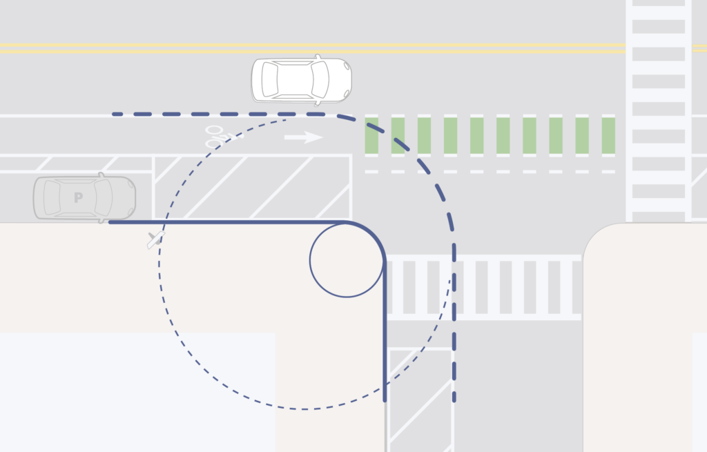
Minimize the corner radius to prevent the managed vehicle from turning too quickly. A corner radius of 5-10 ft (1.5-3 m) is appropriate in urban residential settings and 10-15 ft (3-4.5 m) for other contexts.
In addition to the safety benefits of slower turns, reducing the physical corner radius increases space for people using the bikeway. It can also be repurposed for corner protection islands or slow turn wedges that reinforce the tighter effective radius of the corner.
Corner Islands

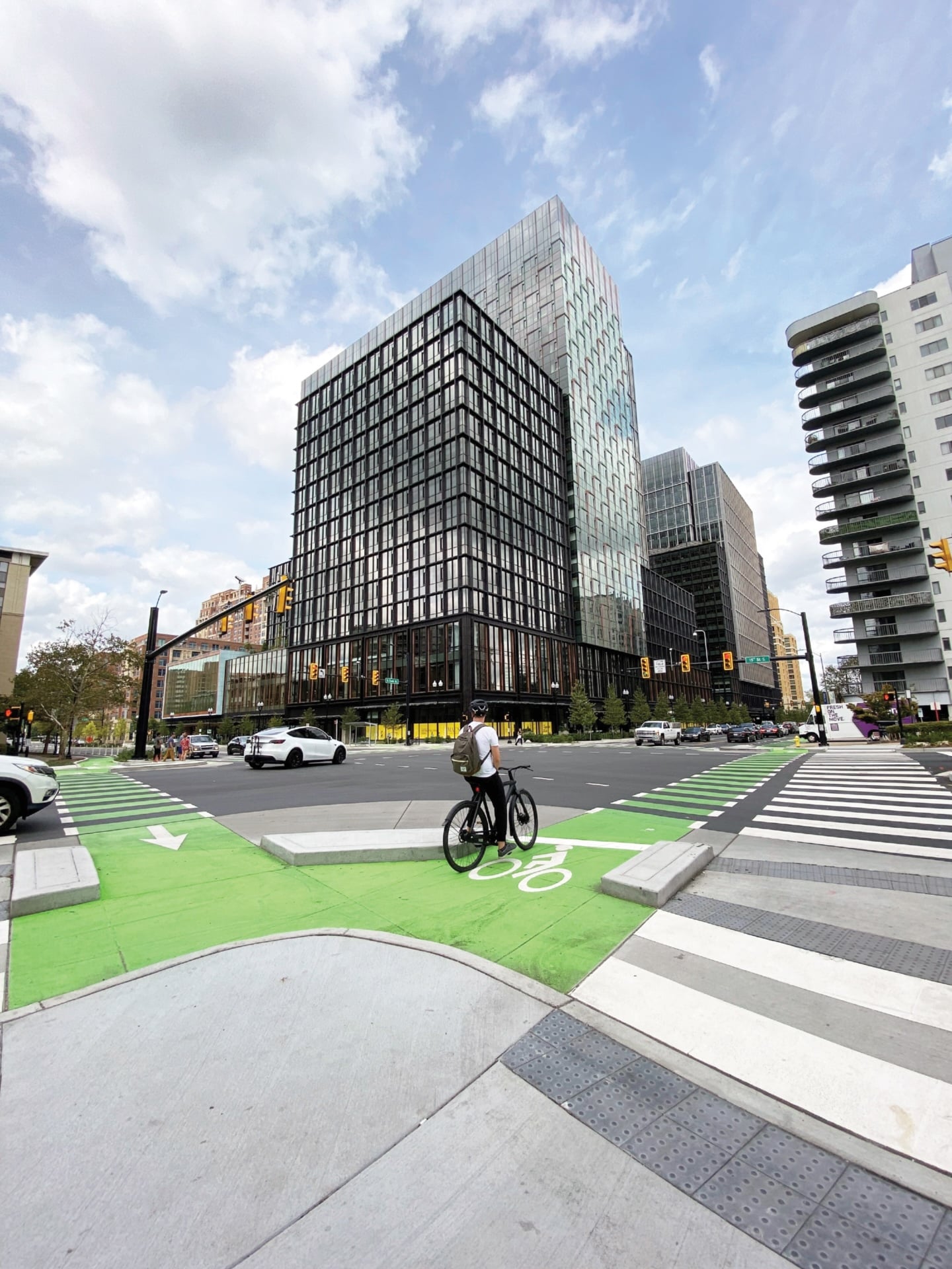
Credit: City of San José
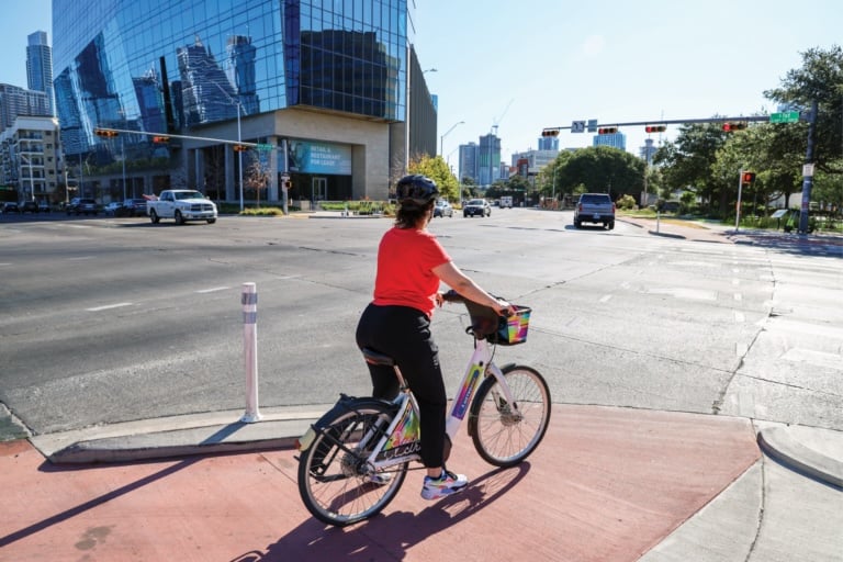
Credit: Austin Transportation and Public Works Department
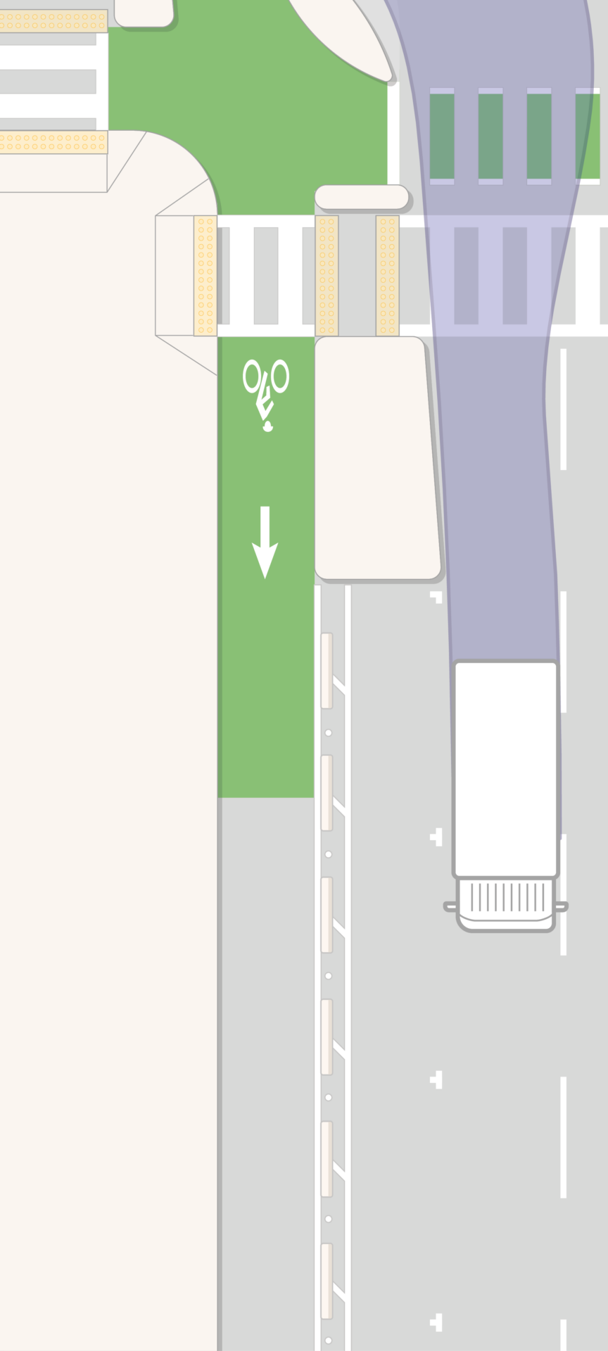
Corner islands limit the turn speed of managed vehicles while allowing the design or control vehicle to make the turn.4 The corner island should limit managed motor vehicle turn speeds to 10 mph (16 km/h) or less.5 The target effective turn radius for managed vehicles is less than 18 ft (5.4 m), usually resulting in a corner radius of 10-15 ft (3-4.5 m).
Corner islands extend bike lane separation into the intersection. In some cases, corner islands can also provide bike queuing areas and create setback space for turning drivers.
If the corner island design does not alone limit managed vehicle turn speeds to 5-10 mph (8-16 km/h), consider including raised elements to reduce motor vehicle turn speeds.
Corner islands are subject to overtracking by some types of vehicles; construct with concrete where feasible. Flexible materials can be used to create corner island treatments6 but will require more frequent repair or replacement.
Single Radius Islands
Single radius islands are designed to guide turns for most vehicles, including both managed and design vehicles. Control vehicles will track over the island. Design single radius islands to be uncomfortable enough to deter overtracking by most drivers but to still be mountable by control vehicles without destabilization.7 People biking or walking are not meant to use or traverse these islands; islands must be completely outside the intended bike or pedestrian path of travel.
Single radius islands are most often used in intersections with only one receiving lane for right turns and are effective across traffic intensities and materials.
When built of concrete, single radius islands should have traversable curbs and a flat top. In some cities, the top is scored or imprinted with a pattern to discourage pedestrian use. Edge lines may be used to increase conspicuousness.
Mountable flexible materials, including modular speed bumps and buttons, should be placed in a diagonal array or perpendicular to the approach path of travel. Pavement markings must be used; typically white, including diagonal lines and an outline of the island. Monitor and modify islands made of flexible materials over time, adjusting the placement of the materials to minimize maintenance and maximize turn-calming effects.
Credit: Elwyn Gonzalez
Dual Radius Islands
Dual radius islands provide a much tighter radius for managed vehicles while having a secondary, wider curb radius that accommodates larger vehicles. The second radius is achieved with mountable elements, typically a truck apron or modular speed humps. People biking or walking are not meant to use or traverse either radius of these islands; islands must be completely outside of the intended bike or pedestrian path of travel.
Dual radius islands are effective in a wide variety of intersection types with different traffic intensities and using various materials.
The inner island must be made of concrete or another very durable material. Its radius must be established with a vertical curb typically at least 5-6 in (125-150 mm). Use the tightest possible radius for this island.
The mountable area should contrast in color, material, or both. Use a mountable or a beveled curb 2-3 in (50-75 mm) tall if building the mountable area with concrete. Without construction, delineate this area with edge line striping and flexible materials, such as modular speed humps. A swept path analysis for the control vehicle determines the outer radius for the mountable area.
Corner islands are infeasible where curb extensions already exist and cannot easily be altered. Bend the bikeway toward the centerline of the street using a preferred taper of 5:1 (maximum 3:1). Provide or continue bikeway separation from the general purpose travel lanes.
Tapered Receiving Islands
An island in the receiving lane can help reinforce safe turn speeds where protected bike lanes intersect. Build the island to match the path of the control vehicle. Tapered receiving islands help ensure that larger vehicles track over the mountable area and reinforce a small turning radius.
Hardened Centerlines and Lane Lines
Credit: Chicago Department of Transportation
Manage turn speeds by ensuring that the receiving leg of an intersection is not overly wide. Reduce the number of receiving lanes, ensure they are as narrow as possible, and harden the centerline or lane lines.
Centerline and lane line hardening refers to vertical or mountable elements placed on the centerline of two-way streets and/or on the lane lines of multilane streets. These elements encourage drivers to turn directly into a single receiving lane instead of turning over a lane line. Centerline and lane line hardening slow both left and right turns.
Priority applications include multilane streets, uncontrolled intersections or midblock crossings, and streets with advanced motor vehicle stop bars to allow truck overturns.
Centerline and lane line hardening can be implemented with flexible materials. Use modular speed humps, narrow rubber islands, flexible delineator posts, or flexible delineator posts mounted on plastic curbs. Constructed median islands and crossing islands can also be used for centerline hardening in projects that include constructed elements.
Extend the hardened line into the intersection straddling the crosswalk regardless of material. Use swept path analysis for the managed and design vehicles to make turns as close to 90 degrees as possible.
- “For pedestrian crashes, the evaluation found a statistical relationship with corner radius. Assuming a baseline condition of 10 ft, the pedestrian CMFs for corner radius for the range of corner radii included in the evaluation went from 1.00 for a 10-ft radius to 1.59 for a 70-ft radius.”
Federal Highway Administration. Crash Modification Factor for Corner Radius, Right-Turn Speed, and Prediction of Pedestrian Crashes at Signalized Intersections. Publication Number FHWA-HRT-21-105. USDOT, 2022: page 2. https://www.fhwa.dot.gov/publications/research/safety/21105/21105.pdf. ↩︎ - “Overall, a designer could conclude from the study that in constant speed scenarios, vehicles are capable of higher turning speeds than the AASHTO equation would predict and an extremely small turning radius would be needed to guarantee low turning speeds.”
Alta Planning + Design. Corner Design for All Users. Alta, 2020: page 7. https://altago.com/wp-content/uploads/Corner-Design-for-All-Users_Alta_Oct-2020.pdf. ↩︎ - Federal Highway Administration. Crash Modification Factor for Corner Radius, Right-Turn Speed, and Prediction of Pedestrian Crashes at Signalized Intersections. Publication Number: FHWA-HRT-21-105. USDOT, 2022. https://www.fhwa.dot.gov/publications/research/safety/21105/21105.pdf. ↩︎
- Federal Highway Administration. Safety Evaluations of Innovative Intersection Designs for Pedestrians and Bicyclists. Publication Number FHWA-HRT-23-052. USDOT, 2023. https://highways.dot.gov/sites/fhwa.dot.gov/files/FHWA-HRT-23-052.pdf. ↩︎
- “This [right-turn speed] evaluation demonstrated that a protected intersection results in reduced turning speeds with the installation of smaller corner radii.”
Federal Highway Administration. Safety Evaluations of Innovative Intersection Designs for Pedestrians and Bicyclists. Publication Number FHWA-HRT-23-052. USDOT, 2023: page 74. https://highways.dot.gov/sites/fhwa.dot.gov/files/FHWA-HRT-23-052.pdf. ↩︎ - “Experience from New York City and Portland shows that modular speed bumps are an effective retrofit application, requiring no reconstruction of the corners.”
Alta Planning + Design. Corner Design for All Users. Alta, 2020: page 21. https://altago.com/wp-content/uploads/Corner-Design-for-All-Users_Alta_Oct-2020.pdf. ↩︎ - “Experience from New York City and Portland shows that modular speed bumps are an effective retrofit application, requiring no reconstruction of the corners.”
Alta Planning + Design. Corner Design for All Users. Alta, 2020: page 21. https://altago.com/wp-content/uploads/Corner-Design-for-All-Users_Alta_Oct-2020.pdf. ↩︎