
Credit: Owen McGaughey
Protected bike lanes must be separated from other traffic. Cities across the U.S. and Canada have experience with a variety of tools, ranging from quickly installed as a retrofit with no construction to a multi-year capital project.
Vertical separation elements should address the specific problems posed by motor vehicle traffic speeds and curbside demand. Modular, mountable, or flexible means of separation may not provide the same level of comfort as more durable curbs and barriers on streets with higher volumes or speeds. More robust separation should be prioritized where vehicular incursion is more likely, such as on retail corridors and at intersections.
However, providing vertical separation along the bikeway is always an important safety improvement. As the network of protected bike lanes increases within a city or region, plans can be made to implement more durable and permanent solutions.
When selecting the means of separation for a protected bike lane, account for the necessary shy distance on both sides of the bike lane. Shy distance to vertical objects must be fully included within the buffer width and is not part of the rideable bikeway.
Street-Level Protected Bike Lanes
Parking

On-street parking is an effective way to separate a bike lane from adjacent motor vehicle lanes.
A minimum buffer width of 3 ft (0.9 m) is required to accommodate the full swing of a car door and mitigate the potential for injurious crashes, commonly known as “doorings.”
The rideable width of a parking-protected bike lane does not include the 6 in (150 mm) adjacent to the sidewalk curb or the 1-2 in (20-50 mm) adjacent to a gutter pan. Gutter pans are not rideable. Because of the possibility of open car doors, 3 ft (0.9 m) of the buffer area may not be included in the total rideable width.
Additional vertical elements, such as flexible delineators or low barriers, may be installed 0.5-1 ft (0.2-0.3 m) from the parking lane line. Vertical flexible delineators should be paired with low barriers to provide additional visibility at night and after snowfall. Spacing can vary along the bike lane, in response to local conditions and needs. Typically, flexible delineators are placed every 10-40 ft (3-12 m).
Do not use tall barriers along parking-protected bike lanes.
A constructed median may be used to separate parking from a bikeway. In many cases, this median is not wide enough to provide an accessible pedestrian path. Consider a width of at least 2.5 ft (0.8 m) to allow a “step out zone” from parked cars. Along a vertical curb, the rideable width of the bikeway is reduced by 8 in (200 mm). A beveled edge may be used on the bikeway side to reduce the likelihood of pedal strikes; the rideable width is reduced by 6 in (150 mm) along a beveled edge. Use a vertical edge along the parking lane; mountable curbs are not effective in deterring incursion upon the bikeway.
Where parking occupancy is high, midblock vertical elements may not be necessary. This can conserve resources for vertical separation at intersections and conflict points.
Vertical elements should be installed wherever parking is prohibited and to maintain proper visibility zones. (See Improve Visibility at Turn Conflicts – Intersection Visibility Zone.)
In extremely constrained cross-sections, where the bike lane is 4 ft (1.2 m) and the buffer is 3 ft (0.9 m), vertical separation should be used along the entire protected bikeway to keep drivers from parking within the buffer.
Flexible Delineators

Flexible delineators are often used to provide physical separation between the bike lane and the adjacent travel lanes. They have low construction costs and can often be implemented quickly; however, routine replacement is required. (See Regular Maintenance.)
The rideable width of a delineator-protected bike lane does not include the 6 in (150 mm) adjacent to the sidewalk curb or the 1-2 in (20-50 mm) adjacent to a gutter pan. Gutter pans are not rideable. Vertical flexible delineators are typically less than 8 in (200 mm) in diameter and 3-4 ft (0.9-1.2 m) tall. The rideable width is typically reduced by 20 in (500 mm) along vertical delineators due to their height.
The buffer area includes both the width of the delineator and the shy distance. It can vary greatly but is typically at least 2 ft (0.6 m). Increase the buffer to at least 3 ft (0.9 m) where motor vehicle speeds may exceed 25 mph (50 km/h). Consider wider buffers with higher vehicular speeds.
Spacing can vary along the bike lane, in response to local conditions and needs. Typically, flexible delineators are placed every 10-40 ft (3-12 m). Place delineators closer together where there is high curbside demand and on the approach and departure
of intersections.
Vertical elements should be installed wherever parking is prohibited and to maintain proper visibility zones. (See Improve Visibility at Turn Conflicts – Intersection Visibility Zone.) Establish a city standard for flexible delineators to simplify procurement, installation, and maintenance.
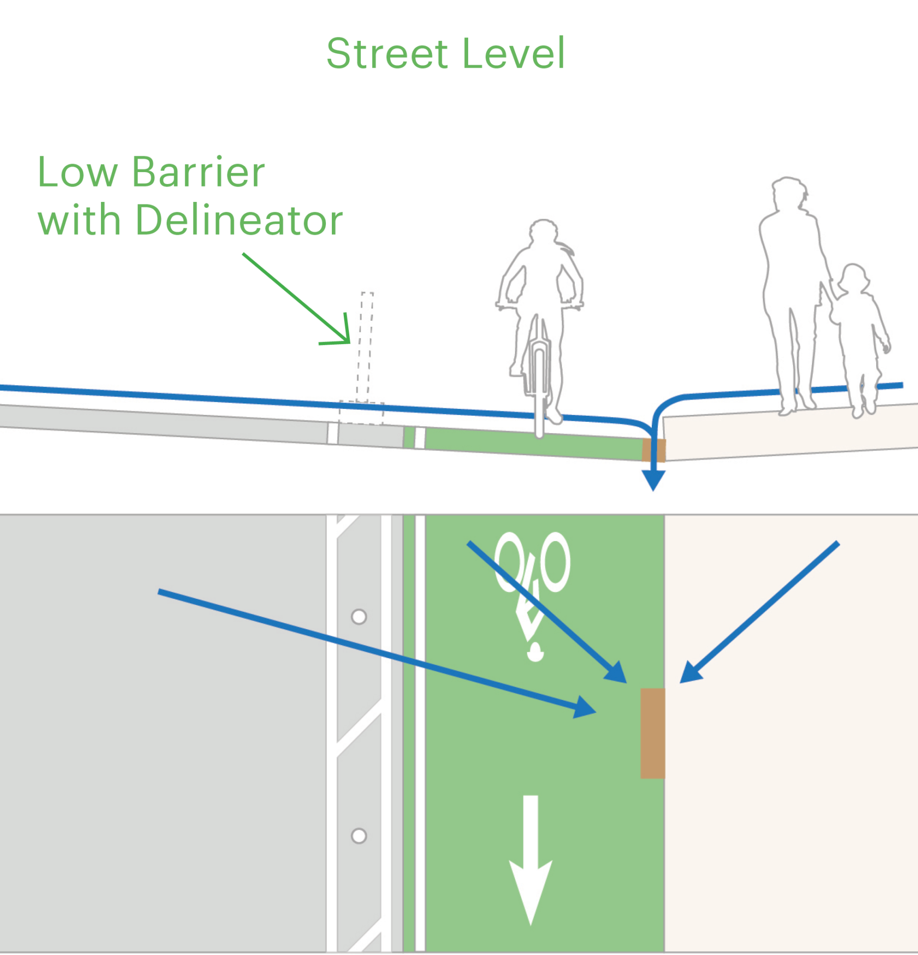
Low Barriers

A growing number of protected bike lanes combine the vertical emphasis of flexible delineators with less-easily traversed rubber parking stops, precast concrete curbs, or cast-in-place or extruded curbs. This combination achieves more comfort than flexible delineator posts alone while still requiring little to no construction. The vertical flexible delineators provide additional visibility at night and after snowfall. They should be installed wherever parking is prohibited and to maintain proper visibility zones. (See Improve Visibility at Turn Conflicts – Intersection Visibility Zone.)
Install vertical flexible delineators on top of the low barriers or mix low barriers with flexible delineators to create a pattern. Modular low barriers, such as parking stops, may be installed 5-20 ft (1.5-6 m) apart. Closer spacing may be preferable based on local needs.
The rideable width of protected bike lanes using low barriers does not include the 6 in (150 mm) adjacent to the sidewalk curb or the 1-2 in (20-50 mm) adjacent to a gutter pan. Gutter pans are not rideable.
The buffer area for low barriers is typically 2-3 ft (0.6-0.9 m). This includes the width of the barrier itself, typically 0.5-1.5 ft (0.2-0.5 m), and the shy distance to the vertical flexible delineators. The buffer also includes an offset between the low barrier and the general travel lane of 0.5-1 ft (0.2-0.3 m). Provide a buffer of at least 3 ft (0.9 m) where motor vehicle speeds may exceed 25 mph (50 km/h). Consider wider buffers with higher vehicular speeds.
Maintenance needs vary based on the type of low barrier installed. Precast curbs may be pushed out of place by vehicle strikes and will require specialized equipment to be replaced. Extruded curbs may erode in wet weather and be damaged by vehicle strikes or plow blades. Modular curbs and flexible delineator posts will need regular maintenance from field staff. (See Regular Maintenance.)
Design low barriers to maintain positive drainage to inlets. Provide adequate gaps to enable water to flow through.
Establish a city standard for low barriers, including any pattern for flexible delineator posts, to simplify procurement, installation, and maintenance. Precast or modular barriers can reduce implementation complexity compared to constructed or cast-in-place curbs. They can be the best solution for retrofit projects without resources for construction.
Mid-Height Barriers

Mid-height barriers, also called tall curbs, are durable and robust means of separating bikeways, even on streets with fast-moving vehicular traffic. Mid-height barriers are pre-cast concrete and typically 1.5 ft (450 mm) tall by 1.5 ft (450 mm) wide at the base. They are installed continuously and do not require crash attenuators, though the end units are typically sloped. Reflectors may be installed along the top for improved visibility at night. A flexible delineator post or object marker may be installed in front of the end piece to improve the conspicuity of the barriers at intersections and driveways.
The rideable width of protected bike lanes using mid-height barriers does not include the 6 in (150 mm) adjacent to the sidewalk curb or the 1-2 in (20-50 mm) adjacent to a gutter pan. Gutter pans are not rideable.
The buffer area for mid-height barriers is typically at least 2 ft 10 in (0.85 m). This is wide enough to provide a 6 in (150 mm) offset to the travel lane, to contain the mid-height barrier, and to provide sufficient shy distance so as to not negatively impact the rideable width of the protected bike lane. Mid-height barriers are typically 1.5 ft (450mm) tall, so the shy distance is 10 in (250 mm). The offset to the travel lane may be increased to 1 ft (0.3 m), widening the buffer to at least 3 ft 4 in (1 m).
Mid-height barriers may be misplaced by vehicle strikes; specialized equipment is required to realign these pieces. (See Regular Maintenance.)
Design mid-height barriers to maintain positive drainage to inlets. Provide adequate gaps to enable water to flow through.
Precast mid-height barriers can reduce implementation complexity compared to constructed or cast-in-place curbs. They can be the best solution for retrofit projects without the resources for construction. Establish a city standard for mid-height barriers to simplify procurement, installation, and maintenance.
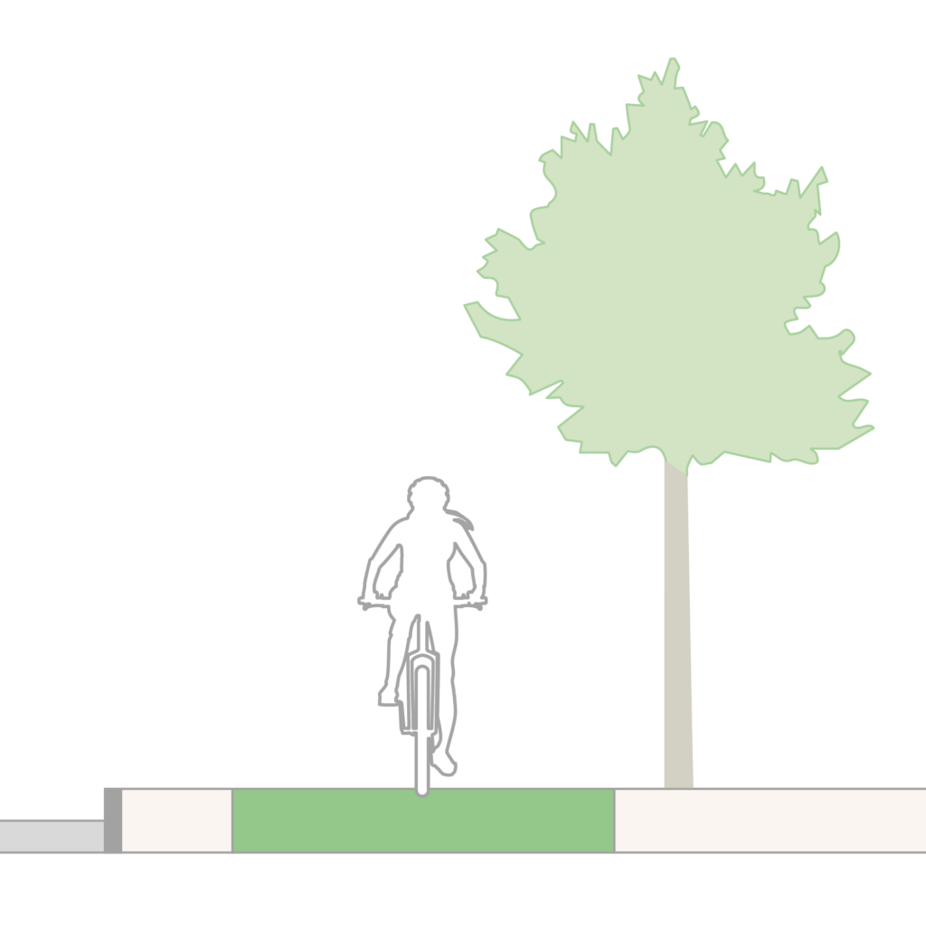
Constructed Medians
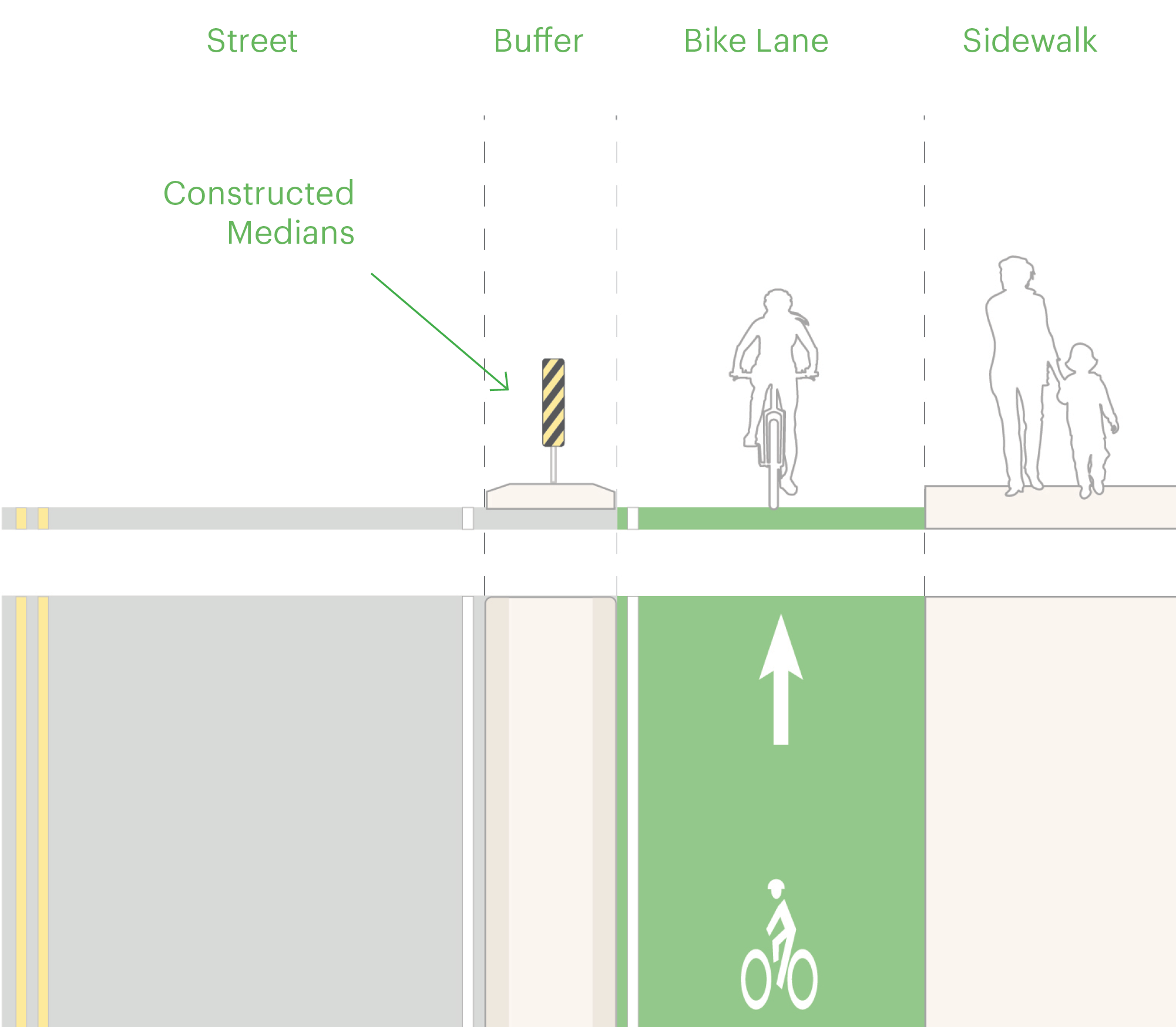
Constructed medians provide robust, high-quality, low-maintenance separation for protected bike lanes. Medians are poured in place and embedded into the roadbed. They can be designed to include green stormwater infrastructure and other landscaping. Their long-term safety and maintenance costs often outweigh their upfront capital costs. Constructed medians should be considered a standard option for retrofit projects or within a reconstruction project.
The rideable width of protected bike lanes with constructed medians does not include the 6 in (150 mm) adjacent to the sidewalk curb or the 1-2 in (20-50 mm) adjacent to a gutter pan. Gutter pans are not rideable.
Constructed medians are typically the same height as other curbs, up to 6 in (150 mm) tall, so the shy distance within the bikeway is 8-10 in (200-250 mm). A beveled edge may be used on the bikeway side of the median to reduce the likelihood of pedal strikes; the shy distance is 6 in (150 mm) along a beveled edge.
Use a vertical curb along the general travel lane. The offset to the travel lane may be increased to 1 ft (0.3 m), widening the buffer to at least 3 ft 4 in (1 m). If a continuous vertical curb cannot be provided along the general travel lane due to emergency access concerns, install flexible delineator posts along the median to discourage other vehicular traffic from entering the bikeway.
Consider an offset of 6-12 in (150-300 mm) to the travel lane. The offset may be included in the travel lane width or provided with an edge line. Marking the edge line is recommended where the median changes widths or is taller than the typical curb height.
Constructed medians should incorporate an object marker, flexible delineator post, or additional reflectors to improve visibility at intersections. Flexible delineator posts and object marker signs are useful in delineating the bikeway after snowfall.
The design of constructed medians must account for drainage. Where possible, provide redundant catch basins or green stormwater infrastructure to reduce rainwater within the bikeway.
Raised Protected Bike Lanes

Credit: City of Somerville
Protected bike lanes may also be designed as raised facilities, either at an intermediate grade or at sidewalk level. Raised protected bike lanes include a buffer along the street curb, separating the bike lane from curbside activity or an adjacent travel lane, and a detectable edge that separates the bike lane from the sidewalk.
Raised bike lanes have long-term safety and maintenance benefits, but are costly to implement unless part of a reconstruction project. They are not inherently a better facility than a street-level protected bike lane.
Raised bike lanes must be visually distinct from the sidewalk. This can be accomplished by making the bikeway of asphalt, porous asphalt, or colored concrete; alternatively, high-friction green surfacing may be applied along the bikeway. Use sawcut joints on concrete bike lanes. Treat any longitudinal seams to provide a smooth surface for narrow and small wheels.

Solid white bike lane lines that are 4-6 in (100-150 mm) wide may be marked on either or both sides of the bikeway.
The cross-slope of the riding surface should be no greater than 3% on retrofits and no greater than 2% for new construction. In limited cases and for short stretches of bikeway, the cross-slope can be up to 8%. The direction of the cross-slope of the riding surface depends on the location of storm drains and any stormwater management elements.
Continue the raised bike lane across minor intersections, driveways of all sizes, and alleys. Where the street buffer is narrow, the bikeway cross-slope can be increased when crossing driveways or alleys; doing so should allow an accessible sidewalk cross-slope.
Any vertical objects should be offset 6-12 in (150-300 mm) from the bikeway and will reduce the bikeway’s rideable width. (See Design Controls for Bicycle Facilities – Rideable Width.)
Because raised bike lanes cannot be easily widened, the rideable width must be maximized from the earliest stages of planning, design, and budgeting. The rideable width of a one-way raised protected bike lane should be at least 7 ft (2.1 m); aim for 8-12.5 ft (2.4-3.6 m) to best accommodate future demand. Bidirectional raised protected bike lanes must be at least 8 ft (2.4 m) with a preferred width of at least 13 ft (3.9 m).
Drainage needs to be planned at the earliest stage of design for a raised bikeway. Consider if the design will use existing or change catch basin locations or incorporate new stormwater management elements such as bioretention areas, bioswales, or other gray stormwater infrastructure. Drainage structures should be located outside of the surface of the bike lane.
Drainage toward the roadway curb is the most common design for raised bike lanes. Inlets or green stormwater infrastructure placed between the sidewalk and the bike lane are especially effective for cities that experience snowfall; the snow melt from the sidewalk and from the roadway can drain without flowing into the bike lane.
Avoid placing utility covers within the bike lane.
Sidewalk Level

Intermediate Level With Raised Median

Sidewalk Level With Green Stormwater Infrastructure

Intermediate Level

Street Buffers

Raised protected bike lanes are separated from general purpose traffic lanes by a horizontal buffer. Intermediate-level protected bike lanes may include this buffer at the same level as the bikeway or above it, at the full height of the curb. Sidewalk-level protected bike lanes have street buffers at the same level as the bikeway, often accommodating plantings or a small furnishing zone.
On urban streets where traffic speeds are 30 mph (50 km/h) or less and without curbside parking, the street buffer should be 2-3 ft (0.6-0.9 m) wide to provide horizontal separation. Where curbside parking is present, this buffer must be at least 3 ft (0.9 m) wide to accommodate open car doors.
Accessible on-street parking creates unique challenges for raised bikeways. Accessible parking spaces must be 13 ft (3.9 m)1 wide, likely requiring the raised bikeway to be rerouted around the parking space. Aim to provide accessible parking at the start or end of blocks, or on the cross streets, to make connections to the sidewalk as easy as possible. If the accessible space is midblock, provide an accessible ramp and pedestrian access path of at least 4 ft (1.2 m).2 The ramp and access path cannot overlap with the bikeway. (See Accessible Parking.)
Signs should be placed in the street buffer where the buffer is at least 2 ft (0.6 m) wide. If wider signs overhang the bikeway, ensure the bottom of any sign is at least 8 ft (2.4 m) above the bike lane.
Sidewalk Buffers
The sidewalk buffer is the space between the bike lane and the sidewalk area. This area is typically at sidewalk level. The sidewalk buffer must have a detectable edge to aid blind pedestrians and people with low vision navigate the street.
Design a continuous landscape or furnishing zone. The sidewalk buffer is a natural place for landscaping, street furniture, lighting, bike parking, and other objects that can help emphasize the separation between the sidewalk and the bikeway. Landscaping or other surfaces not meant for pedestrian passage, also called nonprepared surfaces, must be at least 2 ft (0.6 m). Consult with the local disability community to confirm that the landscaping or surface choice will be appropriate and detectable. Where the landscape or furnishing zone narrows or is eliminated, such as on the approach or departure of intersections where right-of-way may be allocated to turn lanes, install Tactile Warning Delineators.

Construct an intermediate-level bike lane. Intermediate-level bike lanes must have a curb reveal of 2-3 in (50-75 mm) below the sidewalk. Use a vertical curb or a 1:1 beveled curb. Using beveled curbs will result in a wider rideable width than a vertical curb. The shy distance from a vertical curb is 8 in (20 cm) while the shy distance for a beveled curb is 6 in (15 cm). Curb reveals under 2 in (50 mm) are not detectable. Rolled or valley curbs may be detectable, depending on their precise geometry; this method is generally not recommended as a result.

Install Tactile Warning Delineators along the bike lane. Tactile Warning Delineator (TWD) is a raised, trapezoidal surface that indicates the edge of a sidewalk or pedestrian route. TWDs are research-backed and becoming a recommended practice in North America. They provide the same meaning as a curb. Their trapezoidal cross-section makes them traversable by bike even at an acute angle. Install TWD along any sidewalk-level bike lane that does not have a sufficiently wide furnishing or planting zone. TWD should also be installed along boarding islands and shared boarding areas. (See Transit Stops.) Extend TWD to the intersection.
Tactile Direction Indicators should not be used to demarcate the edge of a sidewalk or pedestrian path of travel.
Constrained Raised Bike Lanes

In narrow rights-of-way where measures have been taken to right-size the lanes to the traffic volume, and where vehicular speeds have been managed managed to 25 mph (40 km/h) or under, a constrained raised bike lane may be appropriate.
Raised constrained bike lanes do not provide adequate bikeable width for side-by-side riding, platooning, and passing. Do not install raised constrained bike lanes adjacent to on-street parking.
The raised bikeway and street buffer should be constructed at the same level. The combined width of the bike lane and street buffer should be 6-8 ft (0.2-0.6 m), typically configured as a 1-2 ft (0.3-0.6) street buffer and 5-6 ft (1.5-1.8) bike lane.
Transition raised constrained bike lanes to street level on the approach and departure of signalized intersections or where raised crossings are not feasible. Provide vertical separation with flexible delineator posts in these spaces to maintain protection for the bike lane.
Raised constrained bike lanes may be at an intermediate height or at sidewalk level. At an intermediate height, incursion from motor vehicles is more likely. If the raised constrained bike lane is at sidewalk level, provide a detectable edge to help pedestrians with vision disabilities distinguish the sidewalk from the bike lane.
Mark an edge line along the bike lane to help distinguish the location of the curb edge. Marking an edge line in the travel lane is optional.
Raised constrained bike lanes may require specialized equipment for sweeping and snow plowing, as standard vehicles (even those used for other protected bike lanes) will be challenging to operate. Additionally, the lack of a street buffer means debris and snow pushed from the general travel lanes may end up on the bike lane.
- US Access Board. Public Right-of-Way Accessibility Guidelines. US Access Board, 2023: Section R310.2.1 Dimensions. https://www.access-board.gov/prowag/technical.html#r31021-dimensions. ↩︎
- US Access Board. Public Right-of-Way Accessibility Guidelines. US Access Board, 2023: Section R302.2 Continuous Clear Width. https://www.access-board.gov/prowag/technical.html#r3022-continuous-clear-width. ↩︎