
Roundabouts and neighborhood traffic circles are desirable for intersections along bikeways to slow speeds and promote mutual yielding behavior. They reduce crash severity by limiting conflict points and fully eliminating the challenges of left turns. Intersection delay for people on bikes is shorter than at signalized intersections because all modes move at a consistent, slow pace.
Roundabouts are a type of circular intersection; distinguished by a small footprint, yield-controlled entries, and speed control. While the central island is often circular, it can be made ovoid or distorted to address the particular needs of an intersection.
Roundabouts can be designed as single-lane, multi-lane, or mini-roundabouts. Single-lane roundabouts have a single entry and exit lane on each approach and a single circulating lane all the way around. Multilane roundabouts have multiple entry, exit, or circulating lanes on one or more approaches. Roundabouts with a mix of single and multilane entries and exits or a mix of single and multilane circulating lanes are sometimes called “hybrid” roundabouts. All roundabouts have a central island, which often includes a non-traversable portion and a truck apron that is traversable by large vehicles. As roundabouts decrease in size, the traversable portion of the central island becomes proportionally larger; when the traversable portion takes up the entirety of the central island, the single-lane roundabout becomes a mini-roundabout.
Neighborhood traffic circles are typically located at intersections of local or residential streets, often as retrofits. Neighborhood traffic circles feature a non-traversable center island. Speed control is typically less pronounced at neighborhood traffic circles than at roundabouts. The circle does not include a truck apron but may be designed to be fully mountable for larger vehicles. All legs of the intersection should be yield-controlled.
Bike facilities at roundabouts and circular intersections should provide network connectivity while matching or exceeding the safety and comfort levels of planned or existing facilities on the approach legs. Typically, roundabouts should be designed with protected bike lanes that are separated from sidewalks and travel lanes. Mini-roundabouts and neighborhood traffic circles generally feature shared lanes and their approach legs should include traffic-calming and low traffic volumes, aligned with bike boulevard thresholds.

Credit: Radu Nan, Kittelson & Associates, Inc.
Designing Roundabouts
Roundabouts are an appropriate intersection type in many contexts. A roundabout will often outperform other intersection types when using a 24-hour traffic volume framework (rather than focusing on peak-hour conditions) or when considering life-cycle benefits and costs, including potential safety improvements. However, roundabouts should not be placed too near a signalized intersection as the signal may meter traffic flows to block the roundabout. A coordinated system may be less effective if roundabouts are placed within its extents.
Roundabouts can provide gateway opportunities, particularly on roadways transitioning between land-use contexts, and roundabouts in sequence have been shown to slow vehicle speeds upstream, downstream, and between roundabouts.
A roundabout typically requires the full reconstruction of an existing intersection or creation of a new intersection. As a result, roundabout designs provide an opportunity to prioritize people walking and biking. While roundabouts may have larger footprints than signalized or stop-controlled intersections, roadway approaches to intersections with roundabouts tend to be narrower since less queue storage space and fewer turn lanes are typically needed. That space can be reallocated to separated bike facilities, more generous sidewalks, and additional landscaping. Construction provides the opportunity to add accessible, perpendicular curb ramps.
Roundabout Size
The size of a roundabout is typically described by the inscribed circle diameter (ICD), which is the distance between the edges of the circular travel way. Carefully consider the design vehicle because larger vehicles significantly impact the potential size of a roundabout. Design vehicles should be selected so that the accommodation of relatively rare movements does not compromise the design of the entire roundabout.
| Roundabout Configuration | Typical Design Vehicle | Common Inscribed Circle Diameter (ICD) Range* | ||
|---|---|---|---|---|
| Mini Roundabout | SU-30 | 45-90 ft | 13.5-28.5 m | |
| Single-Lane Roundabout | B-40 or WB-40 or WB-62 (through movements only) | 65-120 ft | 19.5-36 m | |
| B-40 | 90-120 ft | 28.5-36 m | ||
| WB-40 | 100-130 ft | 30-39 m | ||
| WB-62 or WB-67 (all movements) | 120-180 ft | 36-54 m | ||
| Multilane Roundabout (Two Lanes) | WB-40 | 135-160 ft | 40.5-48 m | |
| WB-62 or WB-67 (all movements) | 140-180 ft | 42-54 m | ||
* Assuming 90-degree angles between entries and no more than four legs. The list of design vehicles is not exhaustive.
The total footprint of a roundabout is also dependent on how many lanes approach and circulate within it. Single-lane roundabouts typically operate with lower vehicle speeds, have fewer conflict points, and are simpler to navigate, design, and maintain than their multilane counterparts.
Avoid selecting a multilane roundabout over a single-lane roundabout, even when long-term traffic predictions suggest that a multilane roundabout may be desirable. While a multilane roundabout is typically safer than a comparable signalized intersection, particularly for reducing serious injury and fatal crashes, a single-lane roundabout provides significantly more safety benefits, especially for people walking and biking. Across the United States, many roundabouts were initially designed for a too-high capacity and needed to be converted from multilane to smaller, single-lane roundabouts. Few, if any, single-lane roundabouts needing conversion to a multilane design exist.
Right-turn bypass lanes, whether continuous or yield-controlled, introduce additional conflict points, particularly with people walking and biking, and should be used with caution. However, bypass lanes are preferred if adding one prevents the need for multiple circulating or exit lanes. A right-turn bypass lane design allows for two separate single-lane crossings and can provide slower design speeds at each crossing. A design speed of less than 25 mph (40 km/h) should be maintained on all right-turn bypass lanes, particularly at all pedestrian and bike crossings. Raised crosswalks are preferred at right-turn bypass lanes.
Speed Control
Roundabouts provide speed control through geometric design. Relatively slow design speeds at roundabout entries (typically less than 25 mph (40 km/h) for single-lane entries and less than 30 mph (50 km/h) for multilane entries) reduce the likelihood of severe crashes and increase the likelihood of drivers yielding to people walking and biking. Designing for even slower entry and exit speeds of 15 mph (25 km/h) improves yielding behavior by 50%.1
A roundabout is designed to achieve the target speed at the roundabout entry. Options for reducing vehicle speeds at the roundabout entry include reducing the size of the entry radius, increasing the size of the ICD, providing horizontal curvature through reverse curves on the approach, offsetting the entry lane alignment left of the central island, or providing vertical speed control through raised bike and pedestrian crossings.
The target speed should account for the conditions and context of the approach roadway. A roundabout in an urban center with slower roadway speeds induced by other geometric or roadside features does not require the same type of speed control on the approaches as a roundabout on a higher-speed roadway. Using multiple speed control techniques can provide even lower design speeds, increasing the likelihood of drivers yielding to people walking and biking.
Raised crosswalks may be used in roundabouts to further improve yielding, slow speeds, and increase pedestrian comfort. Multilane segments of roundabouts require additional crosswalk treatments to be accessible, including raised crosswalks, rectangular rapid flashing beacons (RRFB), hybrid beacons, and/or full signalization.2 Raised crosswalks paired with rectangular flashing beacons are recommended for multilane roundabouts.
Clear Distance
Clear sight lines should be maintained between users at any crossing point. This includes sufficient stopping sight distance for drivers to see all bike and pedestrian crossings on the roundabout approach and yield point. Sufficient stopping sight distance should also be provided from both the approach bike and pedestrian crossing and the circulatory roadway to the next downstream exit bike and pedestrian crossing.
Intersection sight distance at a roundabout should be limited to the minimum required on each approach. Providing longer sight distances increases vehicle speeds and lowers rates of drivers yielding to people walking and biking. Intersection sight distance can be minimized with landscaping, berming, or other raised elements in the central island, by using raised features on the roadway edges, or with splitter islands.
Roundabouts with Protected Bike Lanes

The bike facilities at a roundabout should match or exceed the comfort level of the approaches. If there are separated bike lanes on the approach roadway, separated bike lanes should be provided at the roundabout. Typically, roundabouts in North America have not included bike facilities that prioritize and separate people on bikes, instead using bike ramps to turn sidewalks into shared-use paths. While this treatment may be preferable in some cases, separate sidewalks and bike facilities are more comfortable and offer clearer navigation for people walking and biking, including those with disabilities.
Protected bike lanes should be 6-8 ft (1.8-2.4 m) wide if unidirectional and 10-13 ft (3-3.9 m) wide if bidirectional. (See Designing Bikeways for All Ages and Abilities.)
Protected bike lanes may be designed at street level or as raised bike lanes through a roundabout. Street-level or intermediate-level bike lanes are preferred because they have a consistent detectable edge along the sidewalk. Provide a detectable edge between sidewalks and bike lanes at sidewalk-level that is detectable underfoot and distinguishable from the walking area through texture and color contrast. A Tactile Warning Delineator (TWD) is the most appropriate tool for this condition; avoid using a Tactile Direction Indicator (TDI) or Detectable Warning Surface (DWS). (See Bike Transitions.) Additional buffer space may be needed behind the pedestrian path for lighting, signs, and other street furniture that would otherwise impact the usable width for people on bikes and pedestrians.
Where both pedestrian and bike volumes are low, shared-use paths may be used at roundabouts. Shared-use paths at roundabouts should be 10-12 ft (3-3.6 m) wide. They will be considered bidirectional by users and should accommodate people walking and biking in both directions. Use TDIs and markings to indicate separate directional travel lanes.
All protected bike lanes or shared-use paths should have a buffer of at least 6 ft (1.8 m) to allow room for a queuing area and space to provide a perpendicular bike approach to a crossing. Buffers should be no less than 2 ft (0.6 m) wide. The buffer space will also improve the visibility of pedestrians and people on bikes waiting to cross.
Maintenance vehicles, including vehicles that can clear snow, should be able to navigate all separated bike lanes, shared-use paths, and transitions between bike facilities on roundabout approaches and at the roundabout.
Bike facilities on roundabout approaches, transitions, and at the roundabout should be designed with a minimum inner radius of 5 ft (1.5 m) and a minimum outer radius of 9 ft (2.7 m). An outer turn radius of 11 ft (3.3 m) is preferred in locations with more regular use by people on bikes.
Dimensional Considerations for Bikeways in Roundabouts
| Bikeway Width | Buffer to Travel Lane | Inner Radius | Outer Radius | |||||
|---|---|---|---|---|---|---|---|---|
| Separated Bike Lane |
Preferred: 8 ft | 2.4 m |
Minimum: 6 ft | 1.8 m |
Preferred: 6 ft | 1.8 m |
Minimum: 2 ft | 0.6 m |
5 ft (1.5 m) minimum |
Maximum of: Inner Radius + Facility Width - or - 9 ft (2.7 m) minimum 11 ft (3.3 m) preferred |
||
| Shared-Use Path |
Preferred: 12 ft | 3.6 m |
Minimum: 10 ft | 3 m |
Preferred: 6 ft | 1.8 m |
Minimum: 2 ft | 0.6 m |
5 ft (1.5 m) minimum |
Maximum of: Inner Radius + Facility Width - or - 9 ft (2.7 m) minimum 11 ft (3.3 m) preferred |
||
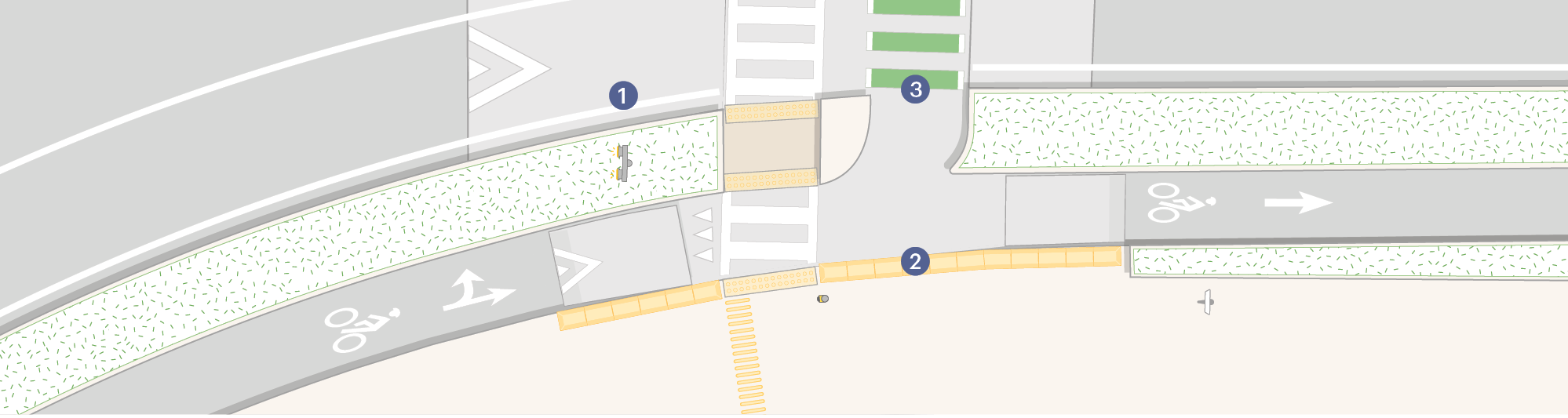
Multilane Roundabout With Raised Bikeway

1Raised crossings with RRFBs are preferred on multilane roundabouts.
2Provide a detectable edge between sidewalks and sidewalk-level bike lanes.
3Bikeway crossings should be separated from pedestrian crossings. Do not place DWS in the bike crossing.
Multilane Roundabout with Street-Level Bikeway
1Raised crossings with RRFBs are preferred on multilane roundabouts.
2Provide a detectable edge between sidewalks and sidewalk-level bike lanes.
3Bikeway crossings should be separated from pedestrian crossings. Do not place DWS in the bike crossing.
Bikeway Transitions
Separated bike lanes should be provided both at roundabouts and on the approach. When transitions are needed to provide additional space between the travel lane and the protected bike lane, or to transition from street-level to an intermediate or sidewalk-level facility, bike ramps should be designed with softer angles and fewer steep ramps.
If the approach roadway has no bike facilities or is a shared street, provide either bike ramps to protected bike lanes or shared-use paths, particularly where total traffic volume exceeds 6,000 vehicles per day. People on bikes prefer protected bike lanes over shared lanes in roundabouts.3
Provide as much distance as possible between pedestrian crossings and bike ramps. A bike transition may be completed as far as 200 ft (60 m) before the crosswalk on a roundabout entry and after the crosswalk on a roundabout exit. A bike ramp should be placed entirely within the buffer between a separated bike lane or shared-use path and a travel lane. Bike ramps should be steeper than curb ramps (a 1:5 slope) to discourage pedestrians who are blind or have low vision from using the ramp.
On the roundabout entry, a bike ramp should use a 45-degree angle (maximum) to a shared-use path or a 30-degree angle (maximum) to a protected bike lane. The roundabout exit approach can use a softer angle of 20-degrees to allow people on bikes to be better aligned with the direction of vehicle traffic. Use a TWD at the top of a bike ramp to provide a continuous edge that discourages pedestrians who are blind or have low vision from using the ramp. Consider using TDIs in the center of the path of travel to provide supplemental navigation.
If transitioning between a constrained bike lane and a raised protected bike lane or shared-use path, the constrained bike lane should approach or depart the ramp at an 8:1 taper. On a roundabout entry, the bike lane line may be dotted for up to 100 ft (30 m) before the beginning of the taper to allow people on bikes to choose to ride in the general travel lanes. On a roundabout exit, the constrained bike lane line may be dotted up to the first 100 ft (30 m) to indicate to drivers that people on bikes may enter the travel lane.
Shared-lane markings can be used in the circulating lanes at single-lane roundabouts. They should be located toward the center of the circulating lane to encourage people on bikes to ride in the middle of the lane. Consider using BICYCLES ALLOWED USE OF FULL LANE (MUTCD R9-20) or DO NOT PASS (MUTCD R4-1) signs in locations where people on bikes are expected to circulate with motor vehicle traffic.
Bikeway Crossings
Bikeway crossings should be separated from pedestrian crossings whenever possible. Separation helps reduce conflicts between modes and allows for sharper angles for people with vision disabilities at pedestrian crossings.
Pedestrian crossings can either be perpendicular to both the entry and exit approaches, perpendicular to the centerline of the roadway, or staggered so that the exit is farther from the circulatory roadway than the entry. Provide appropriate signs and markings to indicate that people on bikes should stop or yield to pedestrians as applicable to state law.
Splitter islands must be at least 6 ft (1.8 m) wide at pedestrian crossings, allowing for the placement of DWS on both edges and clear space in between. In busier locations, consider wider islands to better accommodate groups of pedestrians. Wider islands, of 10 ft (3 m) or more, can also accommodate larger bikes, including cargo bikes and those with trailers.
Bike crossings should be the same dimensions as protected bike lanes, typically 6-8 ft (1.8-2.4 m) wide. Pedestrian crossings can be narrowed to a minimum width of 6 ft (1.8 m) to provide better wayfinding for people who are blind or have low vision. Separated bike lane crossings should be perpendicular to the centerline of the roadway so that people on bikes arrive at the queuing area at a perpendicular angle to approaching motorists. Accommodate the bike queue by widening the buffer between the travel lane and bike lane to at least 6 ft (1.8 m).
It may not be feasible to provide distinct pedestrian and bike crossings in constrained locations with separate bike and pedestrian facilities between roundabout approaches. In such cases, mark a wide crossing of 12-15 ft (3.6-4.5 m) and provide that width through the splitter island and at all curb ramps. Shared-use path crossings should be perpendicular to both the entry and exit approaches or perpendicular to the centerline of the roadway.
Install BICYCLE WARNING (MUTCD W11-1), PEDESTRIAN CROSSING (MUTCD W11-2), or TRAIL CROSSING (MUTCD W11-15 or W11-15a) signs. Where bikeways are bidirectional, install TWO-WAY BICYCLE CROSS TRAFFIC (W16-21P) warning plaques at the roundabout entrances and exits.
Single-lane roundabouts can have street-level or raised crossings for people biking and walking. Provide a DWS for pedestrian ramps leading to and from street-level crosswalks. Do not add them for bikeway crossings. Shared-use paths should have a DWS across the full curb ramp.
Where bikeways are bidirectional, consider using raised crosswalks to reinforce yielding, as drivers may not anticipate people on bikes coming from both directions. Raised crosswalks benefit people walking as well.
Where multilane roundabouts are necessary, raised crossings with actuated rectangular rapid flashing beacons (RRFBs) are preferred. To ensure accessibility, multilane crossings of roundabouts must have at least a raised crossing, an RRFB, hybrid beacons, or full signals.4 The type, location, and design details of these treatments should be considered holistically during the planning and design process. If a hybrid beacon is used on a roundabout exit, the crossing may need to be placed further from the circulating roadway than if an RRFB is used. Further, the location of pedestrian push buttons can be challenging, particularly with separated bicycle facilities between roundabout approaches. In these locations, there needs to be sufficient buffer space along the outside curbline to accommodate signs and push buttons, along with design vehicle movements.
Similar considerations are necessary for the splitter island. If a bikeway is present, people on bikes must be provided full access to, and use of, any crossing device, which may require additional push buttons or passive detection. (See Signal Phasing and Timing Strategies – Bike Signal Design.)
Mini-Roundabouts with Shared Lane Conditions
Mini-roundabouts are small single-lane roundabouts with a traversable central island and splitter islands. The islands can accommodate large vehicles driving over them but are uncomfortable for smaller vehicles to mount. However, in some locations, the intersection’s geometry may warrant a non-traversable central island. Mini-roundabouts control speed while still featuring yield control for bikeways.
Mini-roundabouts are appropriate for intersections with up to approximately 15,000 vehicles per day and relatively few large vehicles. Typically, these intersections have existing all-way stop control or two-way stop control. Converting an intersection to a mini-roundabout is likely to reduce the total number and severity of crashes at the intersection.5
Approach legs to mini-roundabouts should be designed as bike boulevards with intentional speed reduction and volume control measures. (See Bike Boulevards.)
Avoid overly wide circulating lanes; instead, add that dimension to the central island. Use SHARED-LANE markings in circulating lanes, placed in the middle of the lane, typically 5-6 ft (1.5-1.8m) from the curb.
Consider using BICYCLES ALLOWED USE OF FULL LANE (MUTCD R9-20) or DO NOT PASS (MUTCD R4-1) signs ahead of mini-roundabouts to reinforce the expectation that people will ride bikes in the middle of circulating lanes.
Consider placing CIRCULAR INTERSECTION (MUTCD W2-6) signs with ROUNDABOUT (MUTCD W16-12aP) plaques before mini-roundabouts as an educational tool.
Neighborhood Traffic Circles

Neighborhood traffic circles, also known as traffic calming circles, are typically used at the intersection of two low-speed, low-volume streets. Unlike mini-roundabouts, neighborhood traffic circles feature a non-traversable center island. Speed control is typically less pronounced at neighborhood traffic circles compared to roundabouts.
Design approach legs to neighborhood traffic circles as bike boulevards, with intentional speed reduction and volume control measures. (See Bike Boulevards.)
Design the central island to reduce the managed vehicle turn speeds to 5-10 mph (10-15 km/h) while accommodating the design and control vehicles at very low speeds. Curb extensions can help reduce vehicle speeds by requiring more deflection for
entering vehicles.
Traffic circles are typically non-traversable and may include mountable curbs or aprons and landscaping. Any landscaping should not prevent visibility from any direction. Circles may be constructed from temporary materials as an initial installation or demonstration project.
The central island can take a variety of shapes. Where some movements do not exist or are restricted, the central island takes a teardrop or pushpin shape to divert prohibited movements.
The street width and curb return radius of the approaching streets define the design of the traffic circle. The center island can be ovoid where the approach legs have differing widths. Alternatively, use curb extensions to narrow one of the approach legs. Where the approach legs have on-street parking, install curb or sidewalk extensions to force drivers into a position that ensures their path of travel will be deflected as they circulate within the intersection.
| Street Width (A) | Curb Return Radius (B) | Center Island Diameter (C) |
|---|---|---|
|
20 ft (6 m) |
15 ft (4.5 m) |
9 ft (7 m) |
|
20 ft (6 m) |
20 ft (6 m) |
11 ft (3.3 m) |
|
20 ft (6 m) |
25 ft (7.5 m) |
12 ft (3.6 m) |
|
25 ft (7.5 m) |
15 ft (4.5 m) |
15 ft (4.5 m) |
|
25 ft (7.5 m) |
20 ft (6 m) |
16 ft (4.8 m) |
|
25 ft (7.5 m) |
25 ft (7.5 m) |
18 ft (5.4 m) |
|
30 ft (9 m) |
10 ft (3 m) |
19 ft (5.7 m) |
|
30 ft (9 m) |
15 ft (4.5 m) |
20 ft (6 m) |
|
30 ft (9 m) |
20 ft (6 m) |
22 ft (6.6 m) |
|
30 ft (9 m) |
25 ft (7.5 m) |
24 ft (7.2 m) |
|
40 ft (12 m) |
10 ft (3 m) |
30 ft (9 m) |
|
40 ft (12 m) |
15 ft (4.5 m) |
32 ft (9.6 m) |
|
40 ft (12 m) |
20 ft (6 m) |
34 ft (10.2 m) |
|
40 ft (12 m) |
25 ft (7.5 m) |
38 ft (11.4 m) |

Apex curb ramps may need to be reconstructed with the installation of a neighborhood traffic circle. Curb extensions may provide additional space necessary for perpendicular curb ramps.
Use SHARED-LANE markings in the circulating lanes, placed in the middle of the lane, typically 5-6 ft (1.5-1.8m) from the curb.
All legs of the intersection should be yield-controlled. Place YIELD (MUTCD R1-2) signs on each approach.
KEEP RIGHT (MUTCD R4-7b) and OBJECT MARKER (MUTCD
OM1-3) signs within the island are optional.
Consider placing CIRCULAR INTERSECTION (MUTCD W2-6) signs with TRAFFIC CIRCLE (MUTCD W16-12P) plaques before neighborhood traffic circles.
- Geruschat, Duane, and Shirin Hassan. “Driver Behavior in Yielding to Sighted and Blind Pedestrians at Roundabouts.” Journal of Visual Impairment & Blindness 99, no. 5: 286-302 (2005). https://journals.sagepub.com/doi/10.1177/014548 2X0509900504. ↩︎
- US Access Board. Public Right-of-Way Accessibility Guidelines. US Access Board, 2023: Section R306.4.2 Crosswalk Treatments. https://www.access-board.gov/prowag/technical.htmlfr30642-crosswalk-treatment ↩︎
- Singleton, Patrick, and Niranjan Poudel. Investigating Bicyclist Safety Perceptions and Behaviors at Roundabouts. Publication Number MPC-603. Mountain Plains Consortium, 2024. https://www.ugpti.org/resources/reports/downloads/mpc24-516. pdf. ↩︎
- US Access Board. Public Right-of-Way Accessibility Guidelines. US Access Board, 2023: Section R306.4 Roundabouts. https://www.access-board.gov/prowag/technical.htmlfr3064-roundabouts. ↩︎
- Federal Highway Administration. Developing Crash Modification Factors for Mini-Roundabouts. Publication Number FHWA-HRT-23-019. USDOT, 2023. https://highways.dot.gov/media/33861. ↩︎