There are three basic patterns for how water flows into and out of a bioretention facility, if it does not infiltrate through the bioretention facility into the native soil or into a subsurface underdrain pipe.
These patterns are:
- On-line/through-flow
- Combined inflow/overflow
- Raised overflow drain
The design of the inflow, outflow, and overflow path depend on the amount of stormwater runoff that the facility is intended to infiltrate or convey, operation and maintenance requirements, site context, pedestrian and bicyclist safety considerations, and the type of bioretention cross-section.
New York City Department of Transportation
Discussion
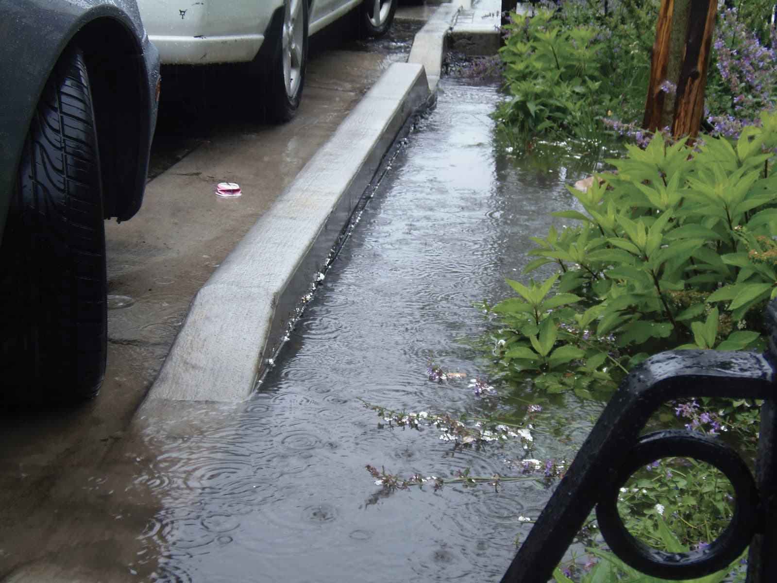
On most streets with a curb, the curb should be continued along the bioretention facility edge. Accommodate water flow into the cell in one of four ways:
- a depression in the gutter and a break in the curb that directs the flow through a graded channel to the facilityâs bottom;
- an inlet;
- a catch basin with a pipe or rectangular channel daylighting into the cell;
- a depression in the gutter that connects to the concrete channel with a trench grate that then outfalls into the cell.
A cell along a curbed street may need one or more inflow points, depending upon the length of the cell, in order to maximize the amount of flow entering the cell and use the full capacity of the facility. Inflows should allow the cell to fill up to its full design ponding depth.
The outflow point serves to direct water back to the street’s gutter or to another cell along the corridor. The inflow point may also act as the outflow point for the facility, depending upon the elevations of the street, inlet, and cell. Alternatively, a storm structure, usually a raised drain, may be placed within the cell to direct the overflow downstream when the cell reaches capacity, or a piped connection to the gray stormwater system for overflow volumes.
The overflow elevation is the maximum ponding elevation; runoff must be directed through an outlet, overflow drain, or bypass and not enter the bioretention area to prevent street or sidewalk flooding.
Critical
The opening and flow path into and out of the cell must be clear of obstructions. Drop the inlet grade 2 inches below the street grade, and allow another 1- to 3-inch drop behind the inlet to allow debris and sediment to settle without blocking the flow of runoff.
Locate other street infrastructure, such as posts for street signs, water meter boxes, valve boxes, and irrigation heads outside of the flow path if they are near inflow and outflow points.
Locate trees and shrubs at least 5 feet clear from the edge of the inlet to allow for tree/shrub growth without blocking flow path and ease of maintenance. Review existing roadway and sidewalk surface grades and regrade or repair any uneven surfaces to ensure that overflow stormwater will flow from the bioretention cell into the street/gutter (or into an overflow drainage structure, if applicable), and not onto an adjacent property or the sidewalk.
Evaluate street grades to confirm that irregularities in the pavement surface do not prevent stormwater runoff or gutter flow from entering or exiting the bioretention facility. Sheet flow off the pavement can easily be unintentionally diverted via a crack or joint in pavement. In retrofit projects, it may be necessary to replace some street pavement to improve water flows from the crown to the gutter, and into the bioretention cell via the curb cut.
On-Line/Through-Flow
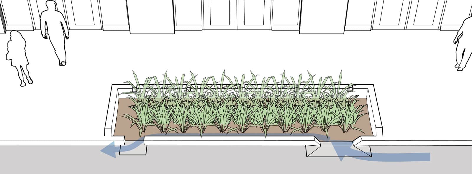
Stormwater flows can be designed to follow a path through multiple bioretention cells along a corridor, especially on streets with a gradual but consistent slope. Stormwater flows in the front (upstream end) of the cell, and excess volume above the designed ponding depth either flows out the back (downstream end) or bypasses the facility.
Through-flow design is most applicable where a series of cells manage stormwater along a corridor.
Enabling stormwater to flow through multiple cells allows the first cell in a series to have the presettling zone for targeted maintenance and then distributes water to other facilities.
On flat streets, to avoid water backing up in the street, the outlet elevation must be 2 inches below the inflow elevation. Otherwise, a raised overflow drain within the facility may be necessary.
Combined Inflow/Overflow
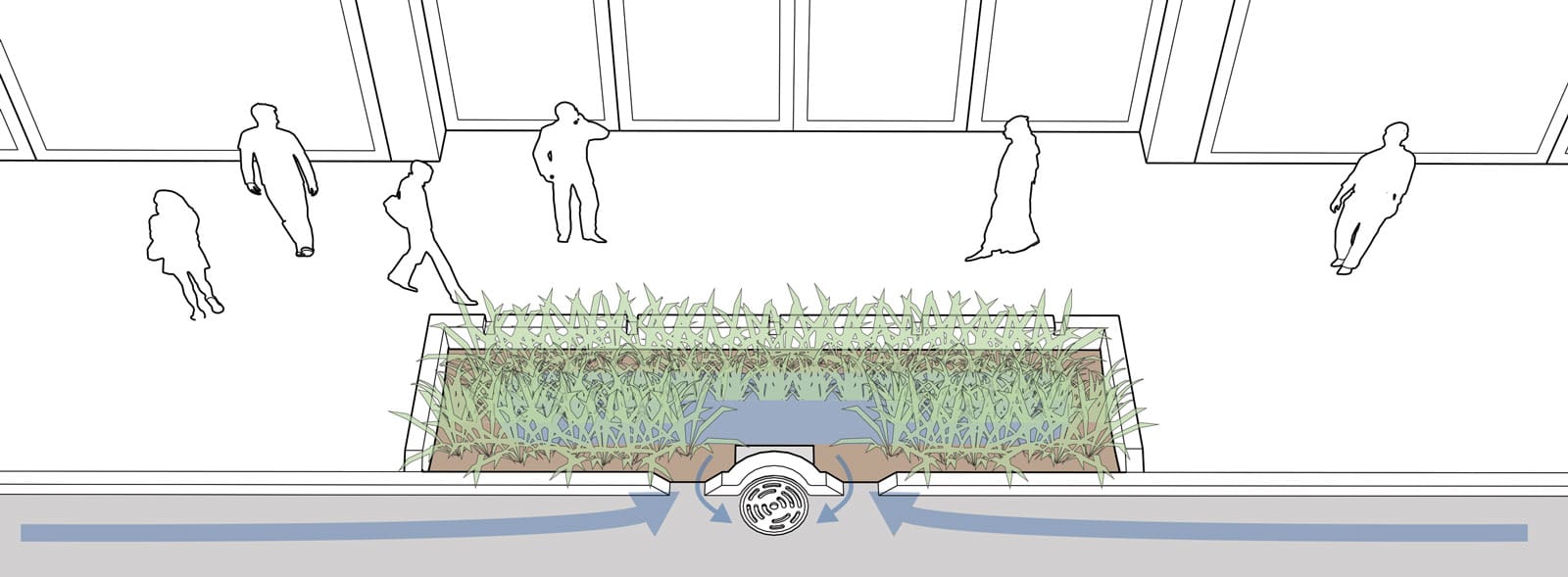
Bioretention cells can be designed so that overflow stormwater simply flows out of the same inlets through which it enters, especially along relatively flat grades.
Cells can be placed over an existing stormwater drain. Place one inlet on each side of the drainage grate to direct overflow into the gray system, with the catch basin at the low point in the street and directing all runoff up to the design volume into the bioretention cell first.
Combined inlets are applicable where each bioretention cell is infiltrating a discreet roadway segment, rather than acting as part of a chain or network diverting along a corridor.
Raised Overflow Drain
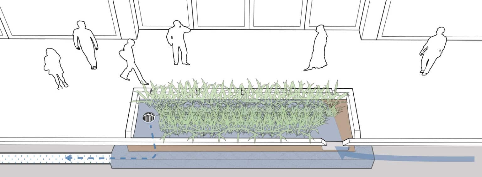
A raised overflow drain such as a “beehive” grate over a catch basin, area drain, or storm structure can be used as the outlet for overflow stormwater. These drains are designed to be level with the maximum ponding depth of the cell. The raised overflow drain should be placed with its rim elevation at the maximum ponding surface elevation.
Overflow is directed into the raised drain, and is piped down to either a stormwater chamber or gray stormwater system.
When using a raised overflow drain in a cell with vertical walls, provide adequate clearance between the outer wall of the structure and the raised drain to accommodate maintenance access.
The space that the overflow structure takes up does not count toward the infiltration area for the facility.