The length-width-height dimensions of a bioretention cell determine the cell’s capacity for temporarily storing stormwater while it gradually filters through the cell’s soil and either infiltrates into the native soil below or is collected in an underdrain pipe and discharged into the downstream system.
How large a cell needs to be depends on the stormwater management goals for the facility and the space available in the right-of-way.
A cell’s footprint area depends on the cross-section type for the bioretention facility and the length, width, longitudinal bottom slope, and planted area of the cell. For facilities with vertical sides, the footprint area is calculated as the bottom area of the cell plus the width of the vertical sides. For facilities with graded side slopes, the facility footprint area includes the bottom of the cell along with the footprint of the area on the sides when the cell is at its maximum ponding depth plus freeboard.
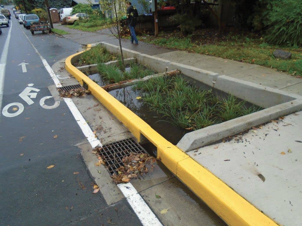
Portland Bureau of Transportation
Sizing and Siting Cells
Bioretention cells are sized and modeled with consideration for factors including the amount of runoff the system is expected to filter downward through the facility’s soil layers (and either infiltrate or collect in an underdrain system) and the amount of space in the street cross-section available for siting green infrastructure. Cell size is also informed by the street context, including factors like the extent of impervious surface area, adjacent land uses and structures, pedestrian volumes, and surrounding topography.
The size of stormwater facilities should account for regional conditions such as climate and weather patterns and local subsurface soil conditions and properties. Cells are typically designed to meet a drainage target of typical storms during a year; during less frequent but more intense rain events, such as a 25-year storm, cell design may allow intense flows to partially bypass the bioretention facility. If a region receives consistent but slow rainfall, and the site has fast-infiltrating native soils, smaller bioretention cells can provide water quality treatment and capture most runoff. Where large storm events are likely, even if infrequent, large bioretention cells or conveyance to large stormwater detention facilities may be desired to reduce peak flow into the graywater system.
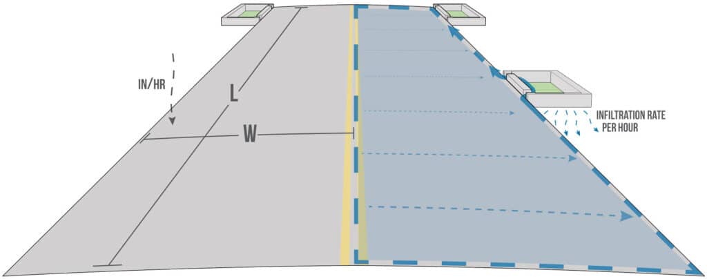
Watershed and existing drainage basin systems affect cell design and size. In regions with combined sewer systems, the primary purpose of cells is generally to capture and infiltrate as much volume as possible to reduce overflows; a large bioretention cell capacity is needed to achieve this goal, usually resulting in a relatively large footprint. In areas with storm systems that have capacity to convey stormwater flows to an open water body such as river or lake, the primary purpose of the cells may be to capture and treat stormwater runoff to protect the region’s water quality, but it is not always necessary to infiltrate all the stormwater for smaller, more-frequent storms.
Bioretention planter cells have vertical walls, providing more capacity for temporary water storage than cells with graded side slopes in the same footprint. However, there are other tradeoffs relevant to the decision to use vertical sides or graded side slopes at a given site.
Where space in the street cross-section is scarce and curbside access is a relatively low priority, long and narrow cells can achieve a high stormwater management capacity. Conversely, where curbside access is a high priority, short and frequent cells can provide a high stormwater management capacity while preserving pathways for people on foot.
To simplify bioretention cell sizing and modeling, cities and regions can develop local sizing charts based on simplified stormwater models. These simplified charts specify the percentage bottom area needed to drain an effective impervious surface area, given a design infiltration rate based on native soils—a useful tool within a reference region.
Key Criteria
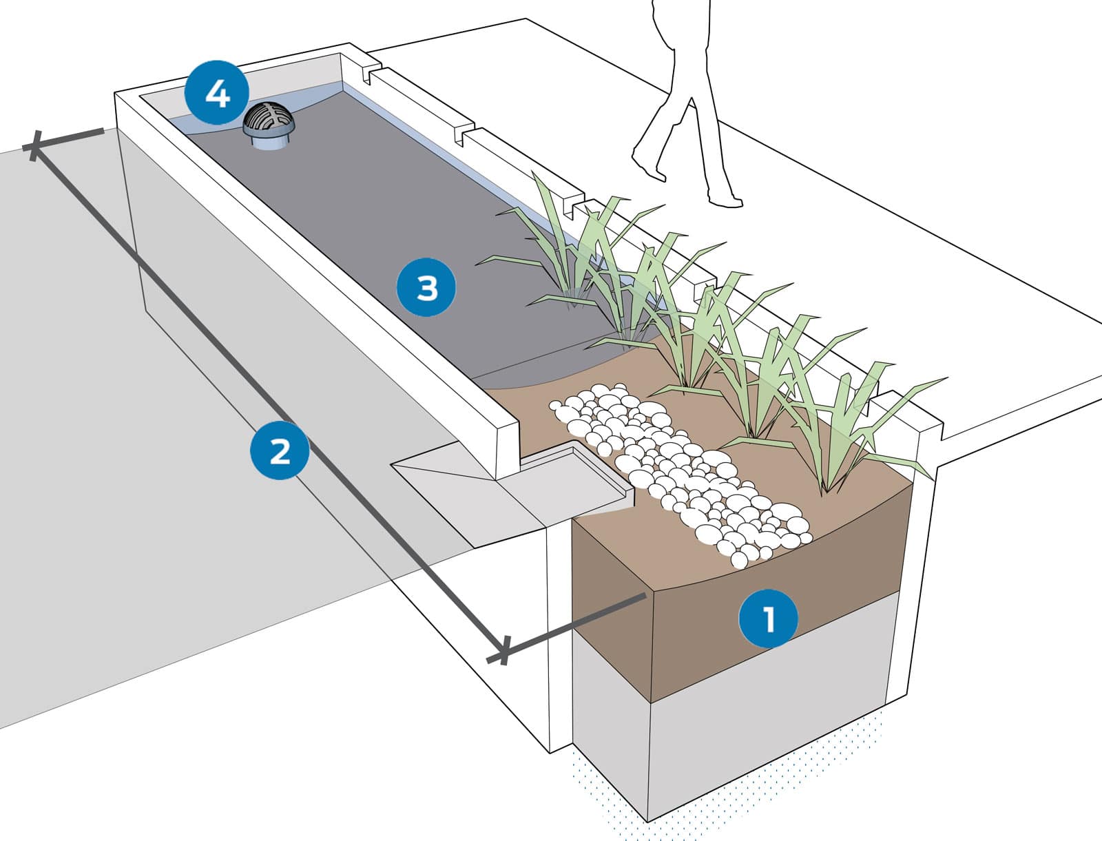
For both vertical walled and graded bioretention cells, a single cell’s or cell system’s ability to infiltrate runoff
effectively relies upon three criteria:
- Cell wetted area footprint;
- Ponding depth; and
- Infiltration rate of underlying and engineered soils.
Bioretention Cell Wetted Area provides the infiltration footprint area of the facility; the wetted area is the surface area at maximum ponding depth of a facility. A larger wetted area maximizes the infiltration area used in sizing the facility. As the bottom area increases, the wetted area increases to maximize the cell’s storage capacity. Engineered soils can increase the bioretention capacity of facilities, providing additional storage.
1For bottom width, 4 feet is a typical preferred minimum for bioretention planters with walled sides; narrower planters may be possible, but these increase the challenge of maintaining healthy plants and are usually less cost-effective to implement, given construction and maintenance costs and performance. For bioretention swales, the minimum recommended bottom width is 1 foot.
2Cell length, or the length of a bioretention swale or planter along the curb, can range from 10 feet to the length of an entire block with intermittent berms. Besides stormwater storage and infiltration capacity, cell length is also affected by longitudinal slope and design infiltration rate of bioretention soil media and native soils.
Aside from managing stormwater runoff efficiently, the length of an individual cell is driven by all-mode curbside access needs. Where parking is permitted, provide for sidewalk access from the curb about every 40 feet, or approximately the length of two parking stalls. Cell crossings can be provided at sidewalk level or may slope down to street level, but they must be above the ponding depth of the cell.
The full bottom length and width of an individual bioretention cell should be used for temporary stormwater storage; where possible, cell design should maximize temporary storage capacity.
A level bottom area accommodates relatively simple maintenance access for routine cleaning and plant care.
On streets with longitudinal slope, install elevated berms or check dams to allow runoff to pond and infiltrate downward through the entire cell bottom area, rather than only flow downstream to the end of the cell.
3Ponding depth provides for temporary storage of the stormwater before it filters downward through the bioretention facility. The temporary ponding depth for bioretention facilities ranges from 2 inches (for mitigating sidewalk runoff alone, or in fast-draining soils) to up to 12 inches (for mitigating roadway runoff, or in slower-draining soils). In areas with moderate to high pedestrian activity (e.g., commercial streets and business districts, and near busy community facilities), limit the ponding depth to 6 inches or install short fencing around the bioretention facility for depths greater than 6 inches.
Vector control issues make drawdown time and maintenance critical from a health and safety perspective. Typically, cells should drain out (have no surface ponding) within 72 hours after the rain event has ended to prevent insect-borne diseases (e.g., mosquitoes breeding cycle).1
However, a 12- or 24-hour drawdown period is often preferable, especially in contexts with regular precipitation (to accomodate the next storm), high pedestrian volumes, or other influencing factors. If fast-infiltrating native soils are present, faster drawdown is also realistic.
4Freeboard depth, measured from the maximum ponding depth to the top of the facility’s overflow elevation, provides a buffer during larger storm events when water overflows the facility and flows into either a storm collection structure or back into the street gutter system through an inlet or curb cut. Freeboard depth is affected primarily by the street grade, and should range from 2–6 inches or greater, depending upon site context, potential for overflow occurrence and its impacts, capacity of the downstream conveyance, the volume of water that the facility is managing (runoff from one block versus multiple blocks), and other engineering or design judgments. Set a deeper freeboard (usually with higher walls) at locations with more-frequent overflows or greater potential impacts.